When use a home back-up power using Generator or Inverter, the peak power usage of the centeral AC is the biggest trouble maker. such as I have been using XW Pro for the whole house back-up, this inverter has 6.8kW continous power and 13.2kW peak power base on the view of Central AC. This inverter can run my 2.5t Centernal AC's Compressor but there are so high tranformer noises.
I have decided to install a soft-starter to reduce the peak power demand when start-up,
My AC's LRA is 67A (16kW), it is too high to handle by my inverter, but, practical usage is just around 40A (10kW). it is why my inverter can support barely. BUT, if there is the other temporary load, my inverter will got damaged if running without a soft-starter.
my AC is not smart enough, and it can be stalled, it means, can lost a key parts.
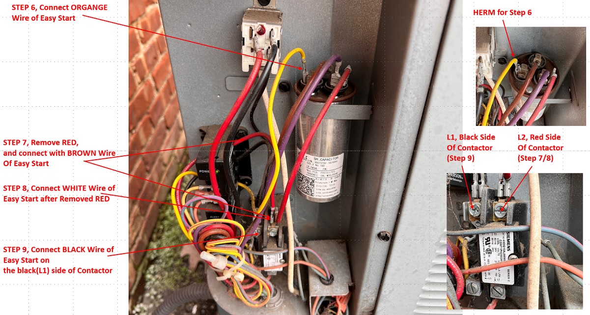
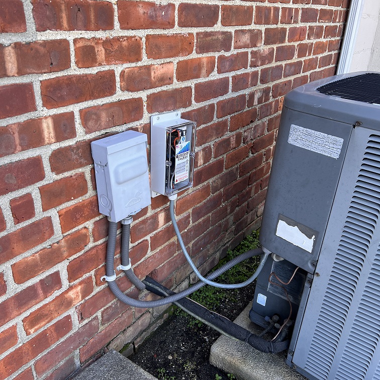
Micro-Air EasyStart 368 is an only solution in the market, this is the connection method
and, final
At the first run with soft-starter
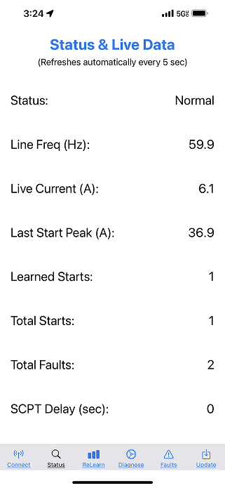
Peak demand is 37A (~9kW),

From the second run, the peak demand has reduced to 18A (~ 4.5kW), not, there is a marginal power for the other loads. and, Motor/Compressor starting power has soften clearly.
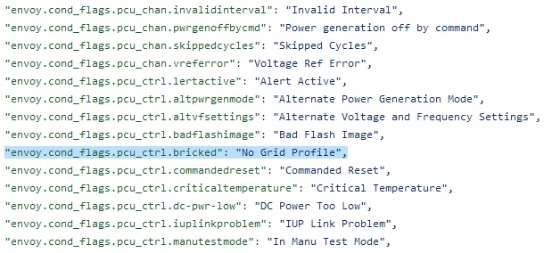
'No Grid Profile' means the inverter has bricked,
and then, recovered by watch-dog reset.
and, 5min start-up delay.
If say a result first, nothing improved yet.
More evidence(users) are complaining Ehphase IQ7+ Inverters are showing Random Produciton Drop with 'No Grid Profile' error with Firmware v4.27 or v4.28. I have thought firmware v4.28 can resolve the issue, but, not.
Now, I decide to change wiring for all inverters to check the difference.
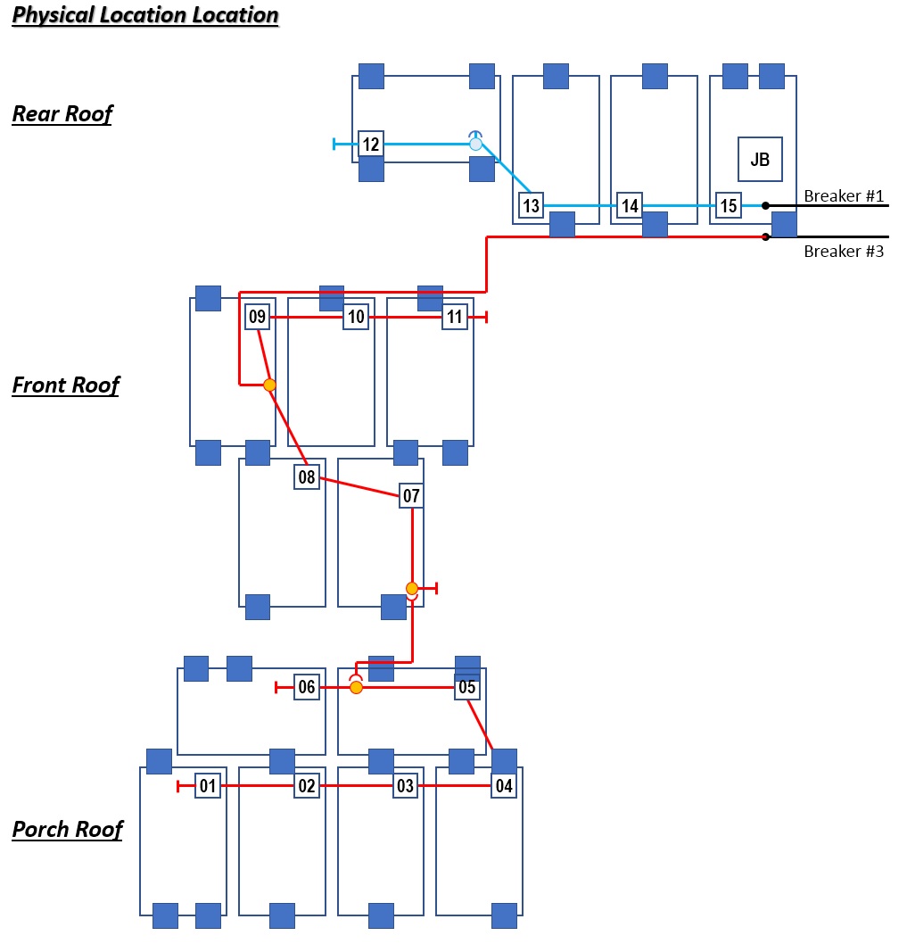
This is the current layout, there is no issue at Rear Roof, Only issue at Front Side Upper/Lower Roof.
So, I just try to simplify the front root layout.
This is the current layout,
i have updated the layout as below
(1) rear roof - I have reduced the Q-cable length by 4'
(2) front roof - change the wiring, and reduce the power on the wire by half. the length has reduced by 4'. and, it is a new wire from roof to load-center usung 10 AWG THHN-2, have installed an independent breaker.
(3) porch - direct to JB, No more path thru on front roof panels, so, the power path have reduced by 12'
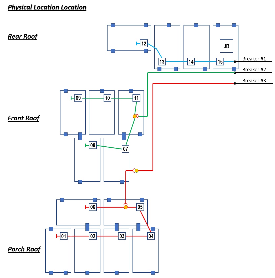
Base on my calculation, this change has lmproved for the voltage rising and interference of panels (inverters).
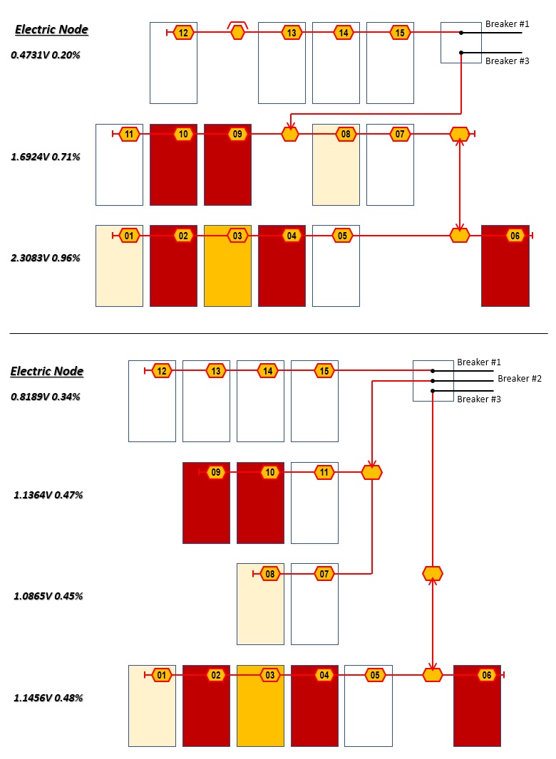
The first day of test, I cannot find any noticeable difference. actually, the inverters are showing error continously. (OTL), but, I wish to compare the difference before/after the layout changes (if there is any improvements)